Top Page > MYDEX Parallel Cam
Parallel Cam Feature This mecahism is the combined with 2 pieces of plate cams and 2 row multiple
cam followers, which is intermittent indexing mechanism to obtain the cam
followers the feeding motion sequentially like a kind of gear. This plate
cam is a kind of conjugate cam, and the shaft of roller gear cam mechanism
is orthogonal while it is characterized by being placed the input and output
shafts in parallel. When dwelling time, alternately mounted 2 pieces of
cam followers are regulated by holding down the 2 pieces of plate cam.
This mechanism as well enables the machine to eliminate the backlash by
adjusting pressurization of the center distance.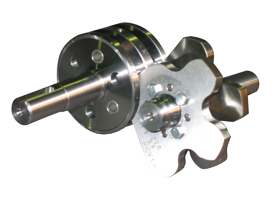

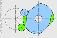
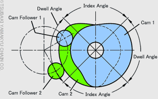
Parallel Cam Mechanism This mechanism as well, cam followers mounted in the turret is always
in the state of regulation, and the montion of the output shaft is determined
by cam rotation. 2 pieces of cams work as "pressing side" and
"holding side", and are transmitted the motion while switching
the roles that depends on the rotational direction or the load working
on the output shaft. And they also keep on hold of the dwell state. The
right figure suggests the middle position of the dwell section, and in
the dwell angle, the rotation is not transmitted to the output and even
the cams are in the state of being unable to transmit the torque. Also,
in index angles are a part of rotating output; therefore, the rotation
is transmitted by the role allocation in which cam type 1 is "pressing
side" and cam type 2 is "holding side"
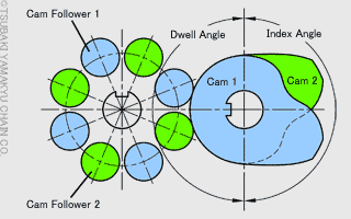
Cams for Indexers
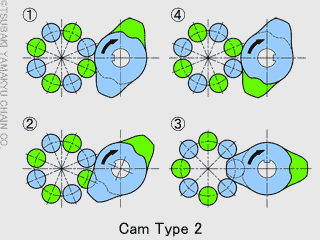
The index and dwell in parallel cam mechanism is shown on the figure below. Standard specifications are used separately as the following number of stops. And it is possible to use 6, 8 stops in cam type 1 as special secifications.
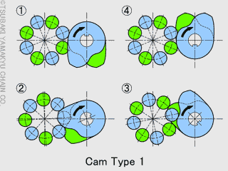
Cams for Oscillators
 An output shaft in the oscillator is being swung back and forth by moving the cam followers along the cam contour. The left figure shows the cam counter that moves 1 reciprocation on every 1 rotation of the input shaft. The cams in index and dwell sections work the same as indexers. The cam counter for 2 reciprocations of the output shafts on every 1 rotation of the input shaft is shown on the figure below.